

NewsKnowledges
ZERODUR® is a low-expansion glass-ceramic used for components where dimensional stability and precision are critical. It is found in optical systems, semiconductor equipment, metrology, scientific instruments, and other precision applications.
However, machining ZERODUR® is not simply a matter of putting the material on a CNC machine and cutting it to size.
In our experience, the difficult part is controlling what happens at the edges, inside holes, beneath the machined surface, and during final grinding.
Small chips, micro-cracks, subsurface damage, or dimensional changes during finishing can affect the final component even when the basic CNC machining appears successful.
For this reason, we plan the machining process around the final drawing requirements rather than treating ZERODUR® as a standard CNC material.
ZERODUR® has a glass-ceramic structure. During machining, material removal can involve brittle fracture rather than the controlled plastic deformation seen in many metals.
This creates several challenges:
The risk is particularly important when a component contains small holes, narrow slots, thin walls, deep pockets, or precision reference surfaces.
This is why machining strategy matters as much as the CNC equipment itself.
ZERODUR® is sometimes treated simply as a type of glass because of its glass-ceramic structure. However, its machining behavior is different from both conventional glass and many technical ceramics.
Technical ceramics such as SiC, Si₃N₄, and alumina can require significant grinding because of their high hardness.
ZERODUR®, on the other hand, presents a different challenge. The material may be easier to remove than some advanced ceramics, but controlling brittle damage and maintaining the final surface condition becomes critical.
Therefore, we do not simply transfer a ceramic machining process directly to ZERODUR®.
Edge chipping is one of the most common problems when machining brittle materials. It typically occurs around sharp edges and hole edges.
For non-critical components, minor edge chipping may be acceptable. For precision components, however, it can affect assembly, sealing surfaces, and optical performance.
This is why edge quality needs to be considered throughout the machining process.
When rough machining ZERODUR® with a diamond grinding wheel, trying to reach the final dimension in the first roughing operation can increase the risk of edge chipping and subsurface damage.
For precision components, our process is therefore typically:
Rough grinding → Precision machining → Controlled allowance → Fine grinding → Polishing and other finishing processes
The remaining material is not simply "extra material." It provides enough allowance for the subsequent fine grinding and finishing processes to remove the machining-affected layer and achieve the required surface condition.
The amount of allowance depends on the component geometry, feature size, required tolerance, surface finish, and machining method. It is determined as part of the process planning rather than using a fixed value for every component.
CNC machining is an efficient way to establish the main geometry of a ZERODUR® component, including holes, slots, steps, curved surfaces, and other complex features.
For most components, our 3- and 4-axis machines can handle parts up to around 400 mm, depending on the geometry. When the component is larger or structurally more complex, 5-axis machining may be required.
However, five-axis machining is not automatically the better choice. It involves more complex equipment and processing, which can significantly increase the machining cost. We therefore select the machining method according to the actual geometry and requirements of the part.
CNC machining also does not mean that every surface can be finished in one operation. When a component requires a higher surface quality, fine grinding and polishing are used after machining to achieve the required surface condition.
In practice, a good ZERODUR® component is often the result of several processes working together—each process is used for what it does best, from rough machining and precision machining to fine grinding and polishing.
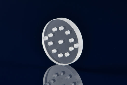
Holes can become particularly challenging when their diameter is small or when the surrounding wall is thin.
During machining, brittle fracture can occur around the entrance or exit of the hole.
For critical holes, the process may therefore include:
The actual process depends on the hole diameter, depth, tolerance, surrounding geometry, and surface requirements.
This is also why we prefer to review the 2D drawing together with the 3D model before finalizing the machining process.
A hole that looks simple on a drawing can become much more difficult when its relationship with a nearby thin wall or pocket is considered.
Not every ZERODUR® component requires five-axis machining.
However, five-axis machining becomes valuable when a component contains:
The main benefit is not simply "more axes."
The real benefit is better control of complex geometry with fewer setups.
For a closer look at how we use five-axis machining for complex ZERODUR® components, see our [ZERODUR® five-axis machining video on YouTube].
Every additional setup can introduce positioning errors.
For a component containing several critical surfaces, reducing the number of setups can help maintain the positional relationship between those surfaces.
We therefore select 3-, 4-, or 5-axis machining according to the actual geometry rather than using five-axis machining simply as a marketing feature.
Chemical treatment has been studied as a method for removing or revealing damaged layers in glass and glass-ceramic materials.
However, chemical etching also removes material. For precision components, uncontrolled material removal can affect dimensional tolerances and surface geometry.
For this reason, chemical treatment should not be considered a universal solution for machining damage.
For precision production, our primary approach is to control the damage during machining and use subsequent grinding or polishing to remove the affected layer when required.
The appropriate process depends on the customer's dimensional and surface requirements.
Some ZERODUR® components require more than dimensional accuracy. The required surface roughness can also determine which finishing process we use.
For a surface roughness requirement around Ra 1.6 μm, a relatively coarse grinding wheel may be sufficient. For requirements around Ra 2.0 μm or above, sandblasting may sometimes be considered. Using a coarser grinding wheel directly on ZERODUR® can increase the risk of chipping or cracking, so the finishing method needs to be selected carefully.
For finer surface requirements, we use fine grinding to bring the surface roughness and remaining material within a controlled range, sometimes down to several tens of microns or a few microns depending on the drawing. The remaining dimensional and surface requirements can then be achieved through polishing.
However, the achievable surface finish also depends heavily on the geometry. Flat surfaces can generally be processed to a very high surface quality with precision equipment. Steps, curved surfaces, and other complex features are more challenging and may require specialized polishing equipment or manual polishing.
Some ZERODUR® components require optical or functional coatings after machining and polishing. In these cases, the coating requirements should be clearly defined on the drawing, including which surfaces need to be coated, the required reflectivity, and the coating type, such as AR coating or other functional coatings.
Based on our experience, the coating performance near the edge of a coated surface can be affected by the coating process, creating an inactive area where the required reflectivity may not be achieved.
For this reason, when the edge area is critical, we may apply the coating before chamfering. The chamfer is then machined after coating, removing the edge area affected by the coating process and leaving the required coating performance on the final functional surface.
Therefore, coating requirements should be confirmed before machining begins. This allows us to consider the coating, chamfer, edge exclusion, and final dimensions together when planning the machining sequence.
At Jundro, we provide precision machining of ZERODUR® components from customer drawings and 3D models.
| Capability | ZERODUR |
|---|---|
| Maximum Size | 500 × 500 mm |
| Flatness | 1/20 λ (Ø300 mm) |
| Concentricity | 0.005 mm |
| Cylindricity | 0.001 mm |
| Parallelism | 0.001 mm |
| Minimum Wall Thickness | 0.2 mm |
| Minimum Hole Diameter | 0.1 mm |
| Minimum Slot Width | 0.3 mm |
| Minimum Internal Thread | M2.0 |
| Polishing | Ra 0.005 μm |
| Sandblasting / Roughening | Ra 3 μm |
A typical precision component may follow a process such as:
Drawing & 3D Model Review
↓
Material Inspection
↓
Rough Grinding
↓
Precision Machining
↓
Controlled Allowance
↓
Fine Grinding
↓
Polishing / Surface Finishing
↓
Cleaning
↓
Dimensional & Surface Inspection
↓
Final Inspection & Packaging
The exact sequence is adjusted according to the component.
There is no single "standard Zerodur machining process" that is suitable for every geometry.
That is particularly important for components with multiple precision features.
If you are developing a ZERODUR® component and are unsure about the machining sequence, edge requirements, holes, thin walls, grinding allowance, or surface finishing, send us your 2D drawing and 3D model.
Our engineers can review the geometry and identify potential machining risks before production.



Chinese (Simplified)

English

German

Japanese

Spanish
Floors 1-2, Building 3, Qianyuan Industrial Park, No. 2 Gaoxin 2nd Road, Dalang Town, Dongguan, Guangdong, China(523770)